Wednesday, March 20, 2024

Voltage Quadrupler for Silicon Photomultiplier (XRF scintillator-detector)

 A Silicon PhotoMultiplier (SiPM) requires about 25-30V to bias it into its avalanche-gain region, so some kind of voltage step-up circuit is needed to boost the power supply voltage.  My current electronics use +/- 10 volts so I need a voltage quadrupler, followed by a low-noise voltage voltage regulator.

I had experienced some noise-injection problems from the boost circuit used in the PocketGeiger, probably from the inductor.  It has to run a noticeable amount of current through the switching regulator's inductor because it also is used to boost 5V to the 9V needed to run the other electronics.  For this reason I have decided to try a charge pump-based voltage multiplier.  This type of circuit can't supply a large current, but the average current drawn by the SiPM will be very small so it should work OK.

I went with a Dickson-style voltage multiplier that uses two inputs that switch between 0 and +10.  The two inputs are 180 degrees out of phase, so a CMOS buffer would work well for this.  Here's an LTSpice simulation of the voltage multiplier:


Due to the relatively small capacitors it takes awhile to come up to its full voltage output.  The simulation was done using 1N914 diodes to get an idea of what the actual voltage output would be, because the voltage drop across each diode reduces the output voltage somewhat.

Since the in-phase and out-of-phase inputs should be balanced for best performance, the oscillator in my actual voltage multiplier needs to have a 50:50 duty cycle.  But this isn't all that easy to achieve.  Most CMOS oscillators based on inverters do NOT have a 50:50 duty cycle.  The other thing I didn't like is that the "best" oscillator I found uses 3 inverters, which used up more gates than I wanted -- producing an unbalanced drive capability for the two inputs to the charge pump.  I really needed a 2-gate oscillator with a guaranteed 50:50 duty cycle.

I recalled that the old transistor-based astable multivibrator produced a pretty good 50:50 duty cycle, so I designed one using two CMOS buffer/inverters, and simulated it using LTSpice.  The circuit initially didn't work because the Spice simulation uses buffers that are exactly the same -- there's no circuit imbalance to get the oscillator going.   I found it necessary to use a pulse generator to kick things off.  The pulse generator just outputs 1 pulse so it doesn't interfere with the simulation after it turns off.

Here's the result:


Since one of the outputs has a 50:50 duty cycle and everything is symmetric, the other output has a  50:50 duty cycle as well.  My initial choice for the R's and C's didn't oscillate at 10KHz, my target frequency, but it was easy to come up with a correction factor (based on the CD4049 Spice model).  That said, my calculations produced:  F = .417/(RC).  This was for a 10 volt supply voltage.  If I drop Vcc to 5V the frequency drops a bit -- to around 7.7KHz.  This is because the buffers' threshold voltage doesn't change as Vcc changes.  Based on the application, the frequency variation would be less of an issue than the fact that the voltage multiplier's output would drop by a factor of 4.  So....no big deal.

My circuit frees up an inverter, only uses one more component than the 3-gate oscillator and has a duty cycle that is much closer to 50:50.  Pretty much a win as far as I'm conerned.

The main variation in the duty factor would be due to tolerance-related variations in the external R's and C's.  Easily addressed by using parts with tighter tolerances, or adding a trimming resistor in series with one of the R's.  The latter approach is NOT preferred because trimmers are more expensive than resistors, and, of course, it's necessary to adjust the trimmer.  Expense would be a hobbyist AND commercial-product related concern, the time needed to adjust the trimmer would be an issue for a commercial product.
 

Friday, March 15, 2024

Gamma Ray Spectroscopy/XRF update

 It's been quite awhile since I posted anything regarding my efforts toward coming up with an inexpensive XRF system.  I have built a lot of hardware and written a lot of software toward that goal, and....so far, have come up empty.  At this point I think it's due to the PIN xray detector -- it's just too noisy, and doesn't appear to have much, if any, energy resolution.  I worked on it pretty hard but....have come to the conclusion that it's not the way to go.  This decision was further cemented by my discovery that the detector is no longer being offered for sale as a standalone device.  It, or a similar-area device, can still be purchased but only in combination with a CsI(Tl) scintillator crystal.  Naturally, it also is more expensive.  And, since it has a very high dark current I still would expect it to be pretty noisy.

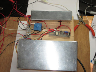
For these reasons I bought a used PMT/Scintillator off ebay.  It is a unit much like this, and can be a very good value if the PMT and scintillator are in good shape.  As-is it's not all that great for XRF usage but there is some good online information on how to modify one so it's compatible with the Theremino hardware and software.  But being a retired electrical engineer and dyed in the wool DIYer I decided to build my own high voltage power supply for the PMT, using a CCFL inverter board to convert 12 volts to 800-900 volts.  Due to lots of EMI coming out of the inverter and the necessity of achieving microvolt-level noise on the HV line that turned out to be quite a challenge.  I ended up using two separate 12V supplies -- one for the CCFL inverter, and a second one for the HV controller board.  The CCFL inverter was modified so its output could be better-controlled, and isolated from the controller board with an optoisolator.  I also made two aluminum enclosures for the inverter and controller, to further reduce EMI coupling from the inverter.

The whole thing was screwed down to a piece of wood, so this is a true "breadboard" style of construction:


The optoisolator circuit is between the two boxes.  The item with the blue tape on it is a home-made inductor to further isolate noise coming from the CCFL's control input line.  I modified the CCFL board by isolating the center tap of the transformer primary.  It normally is connected to the board's +12.  All of the online descriptions of using a CCFL as the heart of a HV power supply simply vary the supply voltage provided to the inverter board, but the one I bought would shut down if the supply went much below 12V.  I also lifted both of the secondary output pins because that completely isolated the CCFL's power supply from its HV outputs, which are routed to the controller board's HV rectifier/capacitor/filter network.

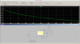
I used LTspice to design the optoisolator.  Here's the circuit diagram and simulation for one of my earlier versions:


The final design also includes a diode-connected PNP transistor in the emitter leg of the power transistor, to improve the low-current linearity of the circuit.  This is important because it turns out that my CCFL inverter doesn't need much input voltage to generate 900 volts.

Here's a photo showing my test setup, minus the HV power supply:


The Am-241 sources, detector and signal conditioning stuff is inside the aluminum box on the right.  The lead shielding is on the inside.  I'm using a Teensy 4.1 with a home-built 1MSPS 16-bit ADC to acquire the pulses.  The Teensy and ADC are behind the computer.  I'm using the Arduino IDE to develop the S/W.  I also am using a little Adafruit TFT to plot the spectums (when I get any that make any sense!).

Regarding the ADC, I figured out that the Teensy 4.1 has 16 contiguous I/O bits in one of its GPIO registers so that made it relatively easy to interface a fast 16 bit ADC to it.  Here's a photo of the ADC board, although in this case it's connected to a T4.0, which only has 8 contiguous bits available -- so the S/W has to grab 16 bits in two 8-bit "gulps" and combine them:

That's all for now.  I'm currently in the process of modifying my PMT's voltage divider.  Once that's done I will be pretty close to trying out the whole system with a detector system that is known to work well for XRF.  From there I get to see if my software is working right....