Sunday, June 21, 2026

Inexpensive miniature "variable reluctance" motors

 I recently bought some cheap brushless motors on ebay, to investigate the possibility of using them in a variation of my paint viscometer.  Since they don't use brushes, they should have much lower running friction -- and therefore be more-sensitive to drag produced by a viscous liquid.

This post is regarding some learnings with respect to those motors.  First, while they are sold as "variable reluctance" motors, they aren't.  That was an easy call, all it took was to inspect the motor.  A variable reluctance motor should have teeth for the motor's stator coils to attract, and the motors I bought do NOT have "teeth".

The other clue is that, since a variable-reluctance motor has no permanent magnets, it shouldn't exhibit any "cogging" when unpowered and rotated by hand.  My motors DO exhibit cogging.

These motors are configured in the standard delta configuration, which only requires three wires.  This is the same wiring that is used in the BLDC's used in hobbyist-style drones.  An ESC would likely work to drive my motors, but sensorless ESC's don't do a good job of running motors slowly -- they sense the induced voltage on an un-driven motor winding to determine the position of the motor magnets, and that voltage is very low at low RPMs -- exactly where my viscometer motor needs to operate.

So the only way to use this type of motor will be to attach something to the motor that provides the necessary angular-displacement information to properly drive the motor.

The other difficulty is that it's not obvious to me (so far) on how to drive this type of motor with constant currents.  The usual motor drive IC's are so-called "H" bridges -- half bridges -- that switch the motor terminals between Vcc and Ground.  No current drive there!  So no back EMF to measure?

At some point I think I just need to build a testbed to see what I can do, in as simple a manner as possible.

Wednesday, June 17, 2026

Paint Viscometer update

 I realized that the value of my sense resistor is too high.  To get a reasonable RPMs value in the range of desireable viscosities, the voltage across it must be about 4.5V.  That caused problems with my 3-comparator circuitry because Vref is only 5V.  The lowest-acceptable viscosity will produce an output voltage that is higher than Vref, that's the core of the problem.

The solution is easy, just (1) change the value of the sense resistor to 25 ohms and (2) reduce the voltage to the motor-control circuit to about 2.25V.  Then the comparator circuitry will have enough range to deal with a low/good/high viscosity range.

Wednesday, June 3, 2026

A DIY paint viscometer


Figure 1 showing my viscometer bench testing setup.  The DVM is showing the motor's back EMF when operating in air.

I bought an HVLP hand-held sprayer for finishing some audio projects I've been working on, and became pretty tired of using the cup viscometer that came with the sprayer.  The cans of water-based paint and varnish I've been getting all need to be thinned in order for the sprayer to deliver a good splatter-free coating.  I don't want to thin-down the entire can -- that's not going to work due to the added volume of water -- and when thinning smaller batches I usually find it necessary to perform the add-water/mix-thoroughly/test several times to get it right.  This adds up to what I think is an unnecessary amount of mess, even before putting on a lick of paint.

So I started thinking about a paint viscometer that isn't so onerous to use and clean.  What I came up with is a variation on a so-called disk viscometer.  This type of device measures the drag a spinning disk experiences when immersed in the liquid-to-be-measured.  Online searching told me that the usual approach is to use a small motor to turn the disk at a set RPM and measure the current necessary to maintain that.  A more-viscous liquid will impose more drag on the disk so the current is approximately proportional to the viscosity.  Calibration is done with liquids of known viscosity at a specific temperature.

I knew I could manage this since I've got a benchtop lathe, mill and 3D printer but knew it would take some time to come up with something that was compact enough (and robust enough) to use for mixing-up paint.  The motor would need to have a tachometer-type system that would output a voltage proportional to the RPMs -- which would then be used in a control loop to set a constant RPM value.  Then I'd need to measure the current flow through the motor.  All that also started looking like an Arduino-style controller to convert the current into viscosity and then generate some sort of output to help guide the paint dilution procedure.

Looking for something simpler, I thought about driving the motor with a constant current.  I knew that the torque a DC motor outputs is proportional to the current flowing through it, so a motor + viscometer disk that is driven with a constant current will spin up until the viscous drag imposed by the liquid on the disk balances the torque produced by the constant current.

This removed the feedback loop needed to maintain a constant RPM value, but didn't remove the need for MEASURING the RPMs.  However, some additional online searching found a discussion regarding a viscometer that used the same constant-current drive scheme I wanted to use.  One of the comments regarding that design suggested that the motor's back EMF could possibly be used as a measure of the motor RPMs.  Now THAT removed the need for a tachometer attachment, basically reducing the viscometer to a constant-current source and some comparators to turn the motor's back EMF into an indication of the paint viscosity.

Here's the circuit design I came up with:


The opamp + transistor on the left form a constant-current source, by forcing a constant voltage across the sense resistor R1.  The motor's back EMF is connected to the three remaining opamps in the quad package, operated as comparators.  The resistor divider network plus the two trimmer resistors are used to set the trip points of the comparators.  Using three glycerine/water mixtures to cover the "acceptable" paint viscosity range gave me the expected variation in the motor's back EMF for the high-to-low viscosity range.  BTW I haven't taken this to the final stage of calculating what the resistor values need to be, but that should be pretty trivial.

The 78L05 is used as a cheap +5 voltage reference to provide a stable current drive to the motor.  

Since the motor back EMF will drop as the RPMs drop, the BEMF is inversely proportional to the paint viscosity.  Due to internal friction and resistive losses in the motor I don't expect it to have a linear relationship but with proper calibration that shouldn't matter.  Calibration over a wider viscosity range plus a polynomial curve fit could turn this idea into a fully-fledged viscometer but I'm after a quick-and-dirty(ish) solution to my painting problem.

I designed a two-sided printed circuit board using the EasyEDA web-hosted tool and a few weeks later I had 5 small PCBs to play with.  It can be seen in the top photo of this blog post, held in the left-hand board vise.

Here's a screen shot of the PCB layout (top side only):

My bench testing showed that I could expect about a 350mV variation in the motor's back EMF for the low/high viscosity range.  That may not sound like much but it will be enough for the purpose.

One thing I haven't mentioned yet is using the spinning disk to mix the paint thinner by shunting the sense resistor with a smaller value, thus increasing the motor current and RPMs.  This would eliminate a messy stirring stick.  And the feature also can be used to clean the disk after the paint has been properly thinned.  Just immerse it in clean water and set the disk RPMs to "high".

The original "disk", as shown in the above photo, was 5cm long -- more of a cylinder than a disk -- and the RPMs in water were so low that I needed to decrease its size.  I eventually went to a 20mm diameter, 5mm thick disk that was printed on my 3D printer.  I had thought that I would need to _increase_ the effective drag coefficient of the disk and had designed some with scalloped perimeters to increase the disk's effective surface area but that turned out to be unnecessary.

My approach differs from the more widely-used approach in that the RPMs are allowed to vary with the viscosity.  This could lead to higher-order nonlinearities due to turbulence and therefore a deviation from the classical Newtonian laminar flow model that commercial viscometers ensure by using low RPMs when testing viscosity.  Again, I'm taking care of all that by restricting my ambitions to testing paint and using a practical calibration approach to set the high/low limits of paint viscosity.


Thursday, August 15, 2024

Ripple/Noise Eater, some simulation results

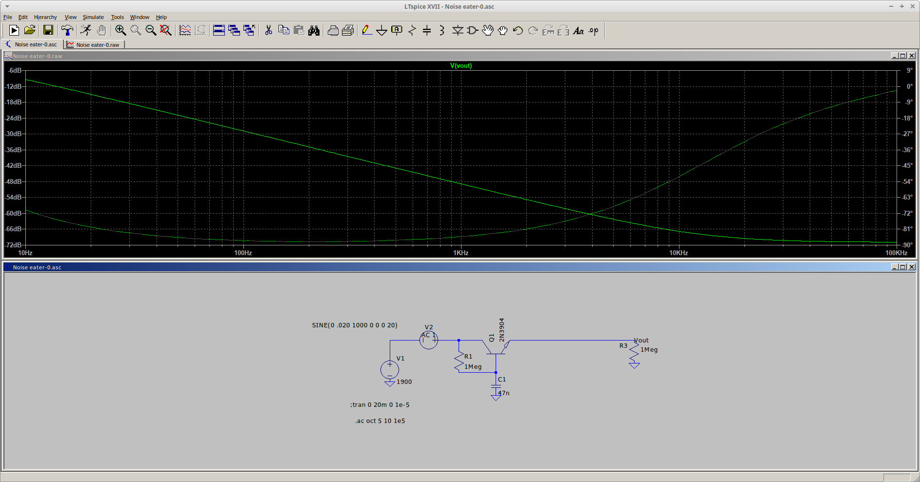
 In my last post I simply described the approaches I explored.  This post shows some simulation results.  The first image below shows the performance of a simple capacitance-multiplier circuit.  It attenuates 60Hz ripple by about 24 dB:


Its main advantage is that it is very simple, using a single transistor to do the job.

And here is the simulation result for my opamp-based version:


This design attenuates 60 Hz ripple a bit more than 72 dB.  That's pretty good.  The design is interesting because the capacitors C2 and C3 are the primary determiners of the circuit's gain, and it is independent of the frequency -- because the ratio of their impedances over frequency remains constant.  The 20 megohm resistor is mostly there to provide bias current for the opamp's inverting input.  It does introduce some rolloff in the circuit's performance at very low frequencies but its impact on noise+ripple at or above 60Hz is negligible.

In a real-world design I would add some protection diodes.  One across the transistor's collector and emitter pins and two connected to the opamp's inverting input.  One connected to the opamp's positive supply and one to either ground or its negative supply.  I probably would choose the negative supply to balance the two diode's leakage currents, but it probably isn't too critical since the opamp is AC coupled to the transistor's base -- so a DC offset on its output wouldn't affect circuit operation.   Unless the offset is so large that the opamp output voltage is close to railing.  But a good diode's leakage current won't be high enough to do that, even with the 20 megohm feedback resistor.

Not shown here, I also looked at the circuit's response to a transient current load to check its response.  I didn't want the circuit to exhibit a lot of ringing, or, worse, burst into oscillation.  It does exhibit a bit of undershoot/overshoot but that disappears when I place a 10nF capacitor between the output and ground.


Wednesday, August 14, 2024

An effective "ripple eater" design

 This post is regarding something that the Theremino approach towards high-resolution XRF spectroscopy emphasizes.  That is the noise+ripple voltage on the PMT (photomultiplier tube) high voltage supply.  They indicate that it should be in the microvolt range because the PMT gain is very dependent on its supply voltage.  This can be a significant problem because the PMT voltage can be in the 1,000 volt range, so we're looking at something on the order of 10^-6/10^3 or a ratio of 1:10^9.  This is a very demanding requirement.  Their approach is to use a passive multiple-order RC filter chain, but this also introduces a large phase shift vs. frequency ( in addition to gain vs. frequency) that is difficult to control in terms of circuit stability.  So its response to a pulse-style load isn't all that great, either.  Thus a lower-order filter scheme looked more attractive in terms of better response to impulse-style loads (as in, the signal generated by a PMT+scintillator when presented with a single x-ray photon).

I've found a few descriptions of a 1-transistor circuit called a "ripple eater" but the circuit wasn't all that intuitive to me.  I also suspected it wasn't the best-possible approach so I tried a couple of different schemes to see what was possible.  But the nice thing was that it offered the possibility of greatly reducing the HV supply's ripple+noise while reducing the order of the filter ... which also would improve the transient response of the HV supply.  So I tried a few different approaches.  The first was a relatively simple "capacitance multiplier" circuit -- basically, an emitter follower driven by an RC low-pass filter.  The idea behind this is that the transistor's base current is low so we can use a very high-value R in the base-input RC low-pass filter.  One very significant limitation with any kind of HV low-pass filter is the fact that high-value and high-voltage capacitors can get VERY expensive, so I limited my options to a maximum of 47 nano-farads.  My SPICE simulation showed that about the best "ripple eater" attenuation I could get with this simple circuit was in the neighborhood of 30dB.  Not too bad, in fact about a reduction of 1000:1.

But we can do much better than that if we use a high-gain, low-noise operational amplifier in a special kind of summing-node application.

More on that soon.

Friday, August 9, 2024

Another XRF Update

 I've used my improved hardware setup (a Scionix PMT/Scintillator detector) to further improve other S/W and H/W components of my experimental XRF system.  I started using the detector and full-bore Theremino-style filter/amplifier setup, but the results weren't all that much better.  I began to suspect some software problems, particularly with regard to the triggering function, so totally re-wrote that portion, switching from a rolling average scheme to a majority-vote approach, where 8 pulses had to exceed the trigger voltage in order to initiate a pulse-detected signal.  That by itself resulted in a significant improvement in the quality of the XRF spectra I was getting.  At that point I was using some Thorium-doped welding rods as test sources.

The other change is that I reviewed the baseline noise coming out of my relatively simple filter + transistor amplifier design that's totally based on the Theremino design.  I had favored it over a low-noise operational amplifier design because the noise voltage coming out of the opamp design was much higher:  but that turned out to be due to the fact that it had much higher gain.  I missed that crucial difference.  Once I reduced the gain in my simulations, the opamp-based design performed substantially better than the discrete transistor design.  So I designed a new filter/amp board using an opamp.  The results were better, but not as good as I had hoped for.  Additional investigation showed that the final RC low-pass filter, which in the Theremino design is just a relatively large capacitor hanging off the emitter of the buffer transistor, was much too "strong" -- the Theremino's emitter-follower's output resistance is pretty low, so even a relatively large capacitor wouldn't exhibit the low-frequency rolloff that my "improved" design did.  So I reduced the value of the capacitor in my new circuit -- and suddenly my XRF spectra became a LOT better.  At this point I can get a pretty decent XRF spectrum for Cadmium at about 23Kev.

But 23Kev is a long ways away from the ~5.6Kev iron XRF peak.  And THAT has remained elusive, because the protective window over my sodium iodide scintillator crystal (in the Scionix detector) appears to crap out somewhere below Cadmium.  I've tried detecting lead, at about 10Kev, and see a small peak -- but that's about the end of the road.

So at this point I have concluded a few things.  First, the Scionix setup was very valuable in terms of improving my software.  If nothing else, it's worth keeping for that alone.  The second is that I need to come up with a different low-energy xray detector.  One approach could be a cooled silicon PIN photodetector.  I've found some made by Osram and Hamamatsu that are fairly large-area, about 3x3mm, with relatively low dark current and relatively low capacitance.  Not too expensive, either.  Cooling them with a 2-stage thermoelectric cooler (TEC) would reduce the dark current and improve the SNR.  So that's one approach, but has its problems when it comes to dealing with condensation.  I want to run the PIN diode well below 0C, so will need to enclose the detector with some desiccant -- or evacuate the interior -- to prevent condensation.  That's do-able, but raises the bar for other folks who want to reproduce this.  Alumina desiccant is good enough and pretty cheap so that probably is the easiest and cost-effective approach.

The other approach is totally different in terms of the detection mechanism.  It uses a gas proportional counter, sort of similar to a Geiger counter, but it's operating voltage is lower so the pulses it generates are proportional to the incident photon energy, rather than being avalanche-multiplied to the point where the tube is saturated (this the Geiger mode).  It's best suited for lower-energy xrays, which is exactly where I want to be in terms of the analysis work I want to perform (figuring out what kind of steel alloy I've got).  If you've got a lathe the detector should be relatively easy to make.  But it requires a continuously-flowing gas mixture of argon and carbon dioxide.  That' not such a big deal, it is about the same as what's used when MIG welding -- but it would be an additional cost for someone who doesn't already have a MIG welding setup.  It also requires a high voltage power supply -- but I already have that, since I needed one for my photomultiplier.  I do NOT have a MIG welding setup, so for now I'm concentrating on a silicon PIN diode.  But keeping this approach in my back pocket.

Saturday, April 20, 2024

Why I love linux

 Linux has an incredibly wide range of useful little applications.  I have a good example of a recent need that was answered by one of them.

Our old Brother HL-5450DN laser printer started having a problem with paper jams.  The troubleshooting guide(s) I went through pointed toward either the toner or fuser components, so I started with replacing the toner -- it's a fast and easy thing to do, plus the old toner cartridge was close to its EOL anyway.  At first that seemed to solve the problem, but not long afterwords the paper jams started again -- and very consistently.  So either we replaced the fuser unit or got a new printer.  Since we try very hard to keep stuff out of the landfill, I went with the first option.  I found a 3rd party fuser on Amazon for a pretty good price (most reviews were positive), and a youtube video on how to R&R the fuser.

The replacement process went very smoothly, and the printer jamming problem appears to have been resolved (fingers crossed).  However, this printer keeps track of the number of prints that go through the machine, and that includes the fuser unit.  At 100,000 pages the printer firmware will start to object to having that "old" fuser unit.  So I needed to tell the computer that the fuser had been replaced.

More online searching revealed references to some utilities that are supposed to do the job:  but I wasn't able to actually FIND any to download.  In addition to that, they are all Windows-centric.  I did find the CDrom that came with the printer, but I didn't find any maintenance-specific applications on it.

My online searching DID find a very useful set of Brother-specific PJL files that are used to perform these kinds of maintenance functions.  PJL stands for "Printer Job Language", and it appears that most network-capable printers understand it.  So what I needed was a way to send the fuser-reset PJL script to our printer.  That's where the "nc" utility came in handy.  nc is linux shorthand for "netcat".  The "cat" command is a linux command that sends text to files or other scripts, so "nc" can send text to networked devices.  This sounded like the ticket.  So I tried sending a little text file to our printer:

nc <ip-address-of--our-printer> 9100 < hello.txt

...and the result was a printed sheet of paper with the words "Hello World!" on it.  BTW 9100 is the port number that's used by most printers for PJL files.

So with this result I substituted the fuser-replacement script I had found for "hello.txt".  I got a "nice" answer from the printer, so I used my browser to access the printer's web page, went to the maintenance section and -- voila! -- the fuser lifetime had been reset to 100%, and the # of replacements had increased from 0 to 1.  It had worked.  And without messing around with any vendor-specific/OS-specific maintenance utility.  If I had actually been able to find it and get it to work under Wine.

Wednesday, March 20, 2024

Voltage Quadrupler for Silicon Photomultiplier (XRF scintillator-detector)

 A Silicon PhotoMultiplier (SiPM) requires about 25-30V to bias it into its avalanche-gain region, so some kind of voltage step-up circuit is needed to boost the power supply voltage.  My current electronics use +/- 10 volts so I need a voltage quadrupler, followed by a low-noise voltage voltage regulator.

I had experienced some noise-injection problems from the boost circuit used in the PocketGeiger, probably from the inductor.  It has to run a noticeable amount of current through the switching regulator's inductor because it also is used to boost 5V to the 9V needed to run the other electronics.  For this reason I have decided to try a charge pump-based voltage multiplier.  This type of circuit can't supply a large current, but the average current drawn by the SiPM will be very small so it should work OK.

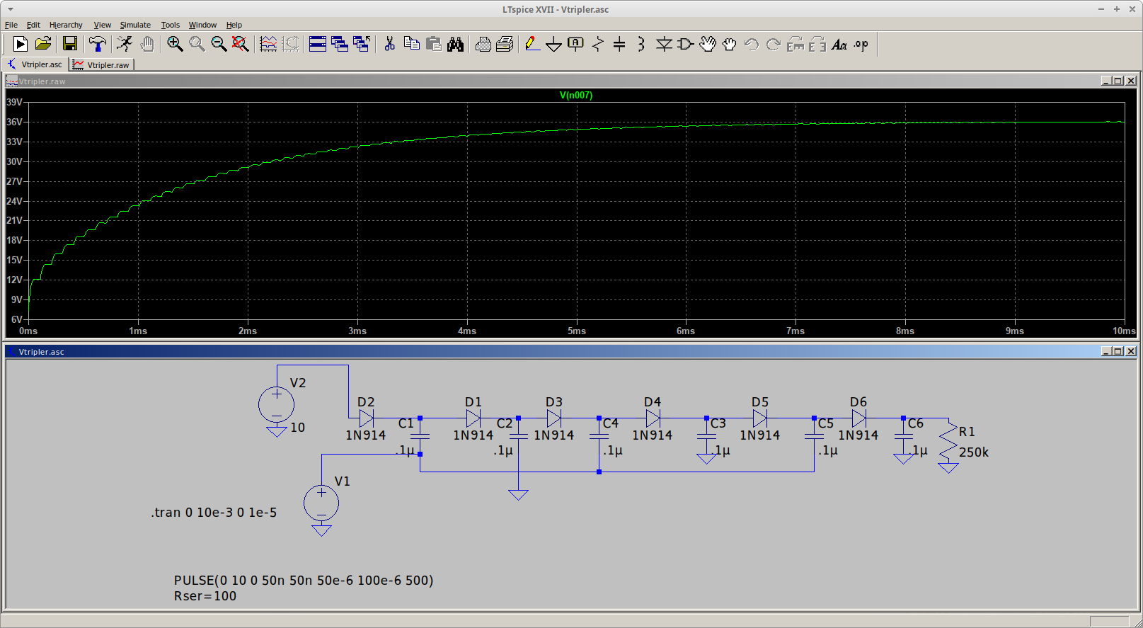
I went with a Dickson-style voltage multiplier that uses two inputs that switch between 0 and +10.  The two inputs are 180 degrees out of phase, so a CMOS buffer would work well for this.  Here's an LTSpice simulation of the voltage multiplier:


Due to the relatively small capacitors it takes awhile to come up to its full voltage output.  The simulation was done using 1N914 diodes to get an idea of what the actual voltage output would be, because the voltage drop across each diode reduces the output voltage somewhat.

Since the in-phase and out-of-phase inputs should be balanced for best performance, the oscillator in my actual voltage multiplier needs to have a 50:50 duty cycle.  But this isn't all that easy to achieve.  Most CMOS oscillators based on inverters do NOT have a 50:50 duty cycle.  The other thing I didn't like is that the "best" oscillator I found uses 3 inverters, which used up more gates than I wanted -- producing an unbalanced drive capability for the two inputs to the charge pump.  I really needed a 2-gate oscillator with a guaranteed 50:50 duty cycle.

I recalled that the old transistor-based astable multivibrator produced a pretty good 50:50 duty cycle, so I designed one using two CMOS buffer/inverters, and simulated it using LTSpice.  The circuit initially didn't work because the Spice simulation uses buffers that are exactly the same -- there's no circuit imbalance to get the oscillator going.   I found it necessary to use a pulse generator to kick things off.  The pulse generator just outputs 1 pulse so it doesn't interfere with the simulation after it turns off.

Here's the result:


Since one of the outputs has a 50:50 duty cycle and everything is symmetric, the other output has a  50:50 duty cycle as well.  My initial choice for the R's and C's didn't oscillate at 10KHz, my target frequency, but it was easy to come up with a correction factor (based on the CD4049 Spice model).  That said, my calculations produced:  F = .417/(RC).  This was for a 10 volt supply voltage.  If I drop Vcc to 5V the frequency drops a bit -- to around 7.7KHz.  This is because the buffers' threshold voltage doesn't change as Vcc changes.  Based on the application, the frequency variation would be less of an issue than the fact that the voltage multiplier's output would drop by a factor of 4.  So....no big deal.

My circuit frees up an inverter, only uses one more component than the 3-gate oscillator and has a duty cycle that is much closer to 50:50.  Pretty much a win as far as I'm conerned.

The main variation in the duty factor would be due to tolerance-related variations in the external R's and C's.  Easily addressed by using parts with tighter tolerances, or adding a trimming resistor in series with one of the R's.  The latter approach is NOT preferred because trimmers are more expensive than resistors, and, of course, it's necessary to adjust the trimmer.  Expense would be a hobbyist AND commercial-product related concern, the time needed to adjust the trimmer would be an issue for a commercial product.
 

Friday, March 15, 2024

Gamma Ray Spectroscopy/XRF update

 It's been quite awhile since I posted anything regarding my efforts toward coming up with an inexpensive XRF system.  I have built a lot of hardware and written a lot of software toward that goal, and....so far, have come up empty.  At this point I think it's due to the PIN xray detector -- it's just too noisy, and doesn't appear to have much, if any, energy resolution.  I worked on it pretty hard but....have come to the conclusion that it's not the way to go.  This decision was further cemented by my discovery that the detector is no longer being offered for sale as a standalone device.  It, or a similar-area device, can still be purchased but only in combination with a CsI(Tl) scintillator crystal.  Naturally, it also is more expensive.  And, since it has a very high dark current I still would expect it to be pretty noisy.

For these reasons I bought a used PMT/Scintillator off ebay.  It is a unit much like this, and can be a very good value if the PMT and scintillator are in good shape.  As-is it's not all that great for XRF usage but there is some good online information on how to modify one so it's compatible with the Theremino hardware and software.  But being a retired electrical engineer and dyed in the wool DIYer I decided to build my own high voltage power supply for the PMT, using a CCFL inverter board to convert 12 volts to 800-900 volts.  Due to lots of EMI coming out of the inverter and the necessity of achieving microvolt-level noise on the HV line that turned out to be quite a challenge.  I ended up using two separate 12V supplies -- one for the CCFL inverter, and a second one for the HV controller board.  The CCFL inverter was modified so its output could be better-controlled, and isolated from the controller board with an optoisolator.  I also made two aluminum enclosures for the inverter and controller, to further reduce EMI coupling from the inverter.

The whole thing was screwed down to a piece of wood, so this is a true "breadboard" style of construction:


The optoisolator circuit is between the two boxes.  The item with the blue tape on it is a home-made inductor to further isolate noise coming from the CCFL's control input line.  I modified the CCFL board by isolating the center tap of the transformer primary.  It normally is connected to the board's +12.  All of the online descriptions of using a CCFL as the heart of a HV power supply simply vary the supply voltage provided to the inverter board, but the one I bought would shut down if the supply went much below 12V.  I also lifted both of the secondary output pins because that completely isolated the CCFL's power supply from its HV outputs, which are routed to the controller board's HV rectifier/capacitor/filter network.

I used LTspice to design the optoisolator.  Here's the circuit diagram and simulation for one of my earlier versions:


The final design also includes a diode-connected PNP transistor in the emitter leg of the power transistor, to improve the low-current linearity of the circuit.  This is important because it turns out that my CCFL inverter doesn't need much input voltage to generate 900 volts.

Here's a photo showing my test setup, minus the HV power supply:


The Am-241 sources, detector and signal conditioning stuff is inside the aluminum box on the right.  The lead shielding is on the inside.  I'm using a Teensy 4.1 with a home-built 1MSPS 16-bit ADC to acquire the pulses.  The Teensy and ADC are behind the computer.  I'm using the Arduino IDE to develop the S/W.  I also am using a little Adafruit TFT to plot the spectums (when I get any that make any sense!).

Regarding the ADC, I figured out that the Teensy 4.1 has 16 contiguous I/O bits in one of its GPIO registers so that made it relatively easy to interface a fast 16 bit ADC to it.  Here's a photo of the ADC board, although in this case it's connected to a T4.0, which only has 8 contiguous bits available -- so the S/W has to grab 16 bits in two 8-bit "gulps" and combine them:

That's all for now.  I'm currently in the process of modifying my PMT's voltage divider.  Once that's done I will be pretty close to trying out the whole system with a detector system that is known to work well for XRF.  From there I get to see if my software is working right....


Wednesday, November 8, 2023

Creamy & Smooth Oat Milk

 This recipe is a variation on ones I found online.  I think it has a much nicer mouthfeel compared to other recipes, because in addition to the oats it contains fat of some kind, like butter or coconut oil (I actually like the coconut oil better).  It also is cooked slightly.  My recipe also adds a small amount of salt and sugar, but they are optional (but recommended).

Creamy Oat Milk

Makes approximately 1 quart of oat milk

2/3C rolled oats.  Not quick (pre-cooked) oats.

1/2 tsp salt

1 tsp sugar

1/2T butter or coconut oil.  They don't have to be in liquid form.

4C water, divided

Optional flavorings:  vanilla or almond extract.  I haven't tried cocoa powder, it probably would require more sugar to balance the bitterness contributed by the cocoa.  Dutch Process cocoa would be less bitter.  These flavors should be added after the oat puree is strained.

1.  Put the oats in a blender.  Add 2 cups water at room temperature, cover with the blender lid and allow to soak for 30 minutes.

2.  Blend on high for 30-60 seconds.  Strain into a bowl with a fine-mesh strainer, using the back of a large spoon to gently press down on the pulp.

3.  Add the remaining water, salt, sugar and fat to the bowl.

4.  Heat on High in a microwave oven, long enough to raise the temperature of the oat milk to 140F.  See Note below.  This step gelatinizes the starch, which gets rid of the gritty mouthfeel.

5.  Use a whisk to blend in the now-liquid fat.  The idea here is that the fat will form something like a roux where the fat globules are surrounded by starch so they will form a relatively stable emulsion.

Higher cooking temperature and more fat might make something closer to cream rather than milk, but if you over-do it you will likely end up with something that is more like pudding instead of milk.

Pour into a 1 quart jar and store in your refrigerator until ready to use.  Shake well before using.  Keeps for about 1 week.

NOTE  Our microwave oven takes about 5 minutes to heat the oat milk to 140F, but ours is an older, lower-powered one.  To check your microwave, place 4 cups of tap water in a bowl and "nuke" it for 4 minutes.  Stir to equalize the temperature and measure the temperature of the water.  If the temperature is higher than 145F, decrease the time by 30 seconds and try again.  If lower than 140F, increase the time by 30 seconds and evaluate the result.  You want to run enough room-temperature water in the bowl so it doesn't affect the result for each trial run.  The final test is to measure the temperature of a batch of your oat milk, since the actual volume of water will be slightly less than 4 cups.

Once you get the temperature to 140-145F you have characterized your microwave.  Make note of the time for the next time you make this recipe.

Tuesday, August 15, 2023

Low-E Materials for Solar Water Heaters

 As part of a liquid desiccant-based A/C system, an inexpensive heat source is needed to regenerate the liquid desiccant (LD).  One of the most-common approaches, used by Tech Ingredients for their exerimental systems, is a solar water heater.  In turn their design is based on one that Desertsun02 came up with, but they have a nice addition, which is to use low-E glass instead of plain glass.  The idea is to increase the efficiency by reflecting the longwave IR that's generated by the hot interior of the water heater back toward the water tubes -- rather than escaping out of the heater.

The problem is that low-e glass isn't all that easy to come by, at least in the searching that I have done.  Most vendors are selling complete low-e window units, while the best source for the odd piece of low-e glass is a custom house.

But it turns out that you can get low-e plastic film to put on a standard window, and it's not all that expensive, either.  So far, so good:  but there are DIFFERENT types of low-e films.  The most common is a film with a thin reflective layer of aluminum, which reflects both visible and IR.  Not useful for a solar water heater.  There is a class of so-called "transparent" low-e films that are available, which might be suitable.  Looking at reviews for these films indicates that the biggest challenge is applying the film without wrinkles or bubbles.  I suspect that the biggest challenge is that the film is being applied to a window that's already installed.  In my case I can lay the "substrate" glass flat, which should make it easier to properly apply the film.

The other potential issue is that the highest-efficiency LD based system requires that the LD be heated to at least 60C to regenerate it.  The film will be exposed to this temperature (via convection on the interior of the enclosure).   How long will it hold up??  Hard to say, since my application is far different from the intended purpose.

Addendum to the DIY A/C addendum

 It's been awhile but after reading my post regarding the use of an indirect-cooled evaporative cooler that's running a pseudo M-cycle scheme, I thought it good to mention that if the incoming water is below the ambient dew point (house interior), at least SOME parts of the system will likely have water condensation on them.  Hoses, any parts of the heat exchanger that isn't getting much, if any, air flow around it, etc.

One reason for re-visiting the subject is, of course, our current heat wave.  It got to 105 yesterday, and probably will get close to that today.  The day after it will "just" get up to 100.

The current outside air is at 77F/25C and 64% relative humidity.  According to my trusty psychrometric chart the wet bulb temperature is about 20C (68F) and the dewpoint is about 17.5C(~64F).  I have observed that the current air conditions are such that the wet bulb and dewpoint temperatures remain the same, as the air heats up.  That means that the humidity ratio (water/air mass) remains the same -- everything is so dry that there's little evaporation occurring!

Thursday, September 15, 2022

Not your usual dehumidifier, an Addendum

I ended my previous post discussing two different approaches that combine an M-Cycle(-ish) style chiller with a liquid desiccant dehumidification system.  One thing I failed to mention regarding the "bootstrap" approach, where the input air to the M-Cycle-Like (hereinafter called the MCL???) is dehumidified using LD, is that, if it works, it should output water that is chilled below the ambient-air dewpoint.  Simply because the water content of the input air is lower.  It remains to be seen if the end result justifies the added complexity of such a system.

The extra-cold water coming out of such a chiller might extract water from interior air to help dehumidify it -- but only if the inside heat exchanger is allowed to cool below the dewpoint.  Since we're running warm interior air through the HX I wouldn't count on it but, since up to this posting I haven't done anything other than make and characterize a plain-vanilla "swamp cooler" style chiller, who knows for sure.  I don't.  

I sort of want it to get cold enough, but don't at the same time, because if it DOES get cold enough to condense water I will need to add a way to take care of the water, rather than let it drip on our expensive wood floors!

Monday, September 12, 2022

Not Your Usual Dehumidifier

 Early in my quest for a DIY A/C system that might actually work in our (often) humid summers I came across a couple of youtube videos produced by Tech Ingredients that led me down an interesting path.

The first one, link here, introduced me to the idea of liquid desiccants.  It used liquid desiccant (LD for short) to pre-dry air that is cooled by flowing through an evaporative cooler.  It was fairly complex, using a second evaporative cooler to cool down the hot and regenerated liquid desiccant (more on this later in my post).  The second one, link here, is a system they built that was (hopefully) sized for a real-world application but didn't work all that well, possibly due to poor efficiency of their chilling tower and desiccant-solution tower.  I think that their spray head scheme didn't work too well -- it's likely that most of the spray quickly wound up flowing down the inner walls of the tube.  The laminar flow of the counter-flowing air then formed a "dead layer" that prevented good contact between the bulk of the air and the water or desiccant.  There are devices called "turbulators" that break up laminar flow into more-turbulent flow that might improve the performance of those towers.

So, what is liquid desiccant (LD) and why is it particularly useful for drying air for A/C purposes?

Folks should be familiar with one-shot desiccants like the silica gel packets found in prepackaged food, vitamins and other food supplements, or products like "Dry-Z-Air", used to capture moisture in locations like RVs, closets etc.  In the latter case, it actually uses the same chemical that is often used in LD applications -- calcium chloride.  I should add that all these desiccants can be regenerated by getting them hot enough to release the water they have absorbed.  I have purchased silica gel beads that actually have an indicator in them to show when they are exhausted and need to be baked so they can be re-used.  And I've seen at least one blog post where someone did something similar with calcium chloride, but it was a pretty dangerous process -- it's necessary to get CaCl pretty hot, and at that temperature it is very corrosive.

There are other solid desiccants like zeolites, some types of clay, molecular sieves etc.  They HAVE been used to perform continuous dehumidification by putting them in a rotating wheel or drum configuration.  One side of the drum is heated and air is passed through it.  The high temperature plus air flow pull the water out of the desiccant.  Then the wheel rotates out of the hot zone into a cool zone, so the desiccant can again absorb moisture.  Then inside air is passed through the wheel and dried.

Systems like this have been used in industrial applications where other process machinery generates high temperatures, so the heat is re-used.  Since the desiccant wheel would need to be heated anyway, this equals a savings in money.  They aren't used for private houses because houses typically don't have that kind of high-quality waste heat available; and they also are pretty large so there's enough capacity in the system to significantly dry the air.

In contrast, LD solutions -- typically they use something among the following:  lithium chloride, calcicum chloride, potassium formate or potassium acetate -- don't require really high temperatures to be regenerated.  In fact, they can be regenerated with systems that are very similar to (good) solar hot water heaters.  This is very attractive because typical demand coincides with lots of sunlight around.  Once your solar LD heater is built, the energy is "free".  Not quite because it has to be pumped through some other apparatus, but that doesn't take much energy to accomplish.

Most research in the field has found that lithium chloride is the most efficient LD.  It also is the most expensive so it's automatically eliminated from my consideration.  Among the rest, calcium chloride probably is the most efficient but it has some problems.  The first is that the solution, which is about 35-40% CaCl, is very corrosive so the pipes, pumps and heat exchangers used to heat and cool it have to be either plastic, stainless steel or ceramic.  This jacks up the price, at least for heat exchangers and pumps.  Of course, its corrosive nature is worse at elevated temperatures so a good design approach is to place our expensive pumps in the loop where the LD is at its lowest temperature.  This would right in front of the regenerator, which heats the LD up in order to shed the water it absorbed.  Another problem is that concentrated CaCl solutions have a very high freezing point, 40F and higher so it's necessary to keep the solution warm enough so it doesn't freeze and stop the system from working.  The other problem also is related to CaCl's  corrosive nature, and that is "carryover".  Since the dehumidifier designs have to put interior air and CaCl solution in intimate contact, there is the possibility of CaCl solution droplets being carried into the interior space, where they can corrode metal and degrade fiber -- like rugs, furniture, clothing....so the design of the absorber portion of the system is very important.  This, by the way, is another problem with the Tech Ingredients approach because they deliberately try to atomize their LD solution.   They are depending on some kind of post-absorber filtration setup, one way or another, to prevent that.  Absorbers that use air flowing at relatively high speeds are particularly susceptible to this problem.

Other LD solutions like potassium formate and potassium acetate are more benign in this regard, but they (1) aren't as efficient, (2) are more expensive; and (3) in the case of potassium acetate, its solution is reported to be very viscous so it is hard to pump it through the dehumidifier system.

It appears that the best way to prevent carryover is to use either packed-bed absorbers or so-called falling-film absorbers.  Unfortunately, the best media for packed beds is pretty expensive -- I calculated that a 1 cubic-meter absorber would require over $2,000 worth of media (basically specially-designed plastic whiffle balls).  So some kind of falling-film scheme looks best.

For developing different types of absorbers I'm planning on sampling the exit air with a high-voltage arc to ionize any calcium ions that are present, to be analyzed with (naturally, a home-made) visible-light spectrometer.  That will quickly reveal if the design has any carryover or not.

The Tech Ingredients' second design is meant to use the same LD solution to simultaneously cool the air and dehumidify it, in contrast to their first design which just dehumidifies the air entering an evaporative chiller.  However, their second design depends on an unassisted evaporative chiller to cool the LD solution -- not viable for a region that has high humidity, since the ability to cool the LD solution is limited.  The problem with their first design is sort of related, because they're using an unassisted evaporative cooler to chill the LD solution.  There are two alternatives that could improve the situation.  First, build an oversized chiller using an air pre-cooler to sorta-kinda replicate a Maisotsenko-cycle system; and use the chilled water to both cool the house and operate an LD dehumidifier's absorber in a separate system to control the house's interior humidity level.  The second is a kind of bootstrap system where the chiller is fed by an outside "feed" air flow that has been dehumidified by an LD system -- which in turn uses the same chiller water.  It's bootstrapped because as the chiller operates the dehumidifier front end, the dehumidifier becomes more and more effective -- it's helping to decrease the wet-bulb temperature because the feed air's RH is reduced by the dehumidifier, so the chiller water temperature goes down and further reduces the RH of the input air.  And so on.  I haven't found any papers that describe a system like this so at this point it is a wild guess on whether or not it is a real improvement or not.

Friday, September 9, 2022

Cycles: The Mysterious Maisotsenko Cycle

 The M-cycle is touted as a new thermodynamic cycle that will solve the world's air-conditioning problems (natch, by the companies selling them).  But is it really that good, and just how does it work?  When I look at drawings of air conditioners that use the M cycle it seems pretty confusing with all the different pieces and "wet channel" and "dry channel" stuff.  Not to easy to figure out, perhaps deliberatly so.  But by looking more closely at our trusty Psychometric chart things start to become much clearer.

If you have looked at my previous blog posts on DIY A/C you have already seen this:


It shows the different "paths" taken by evaporative coolers (solid line) and the more common compressor-based A/C systems, shown by the dotted line.

Suppose we sort of combine them.  Let's add a special type of heat exchanger, very similar to what's called an HRV, a Heat Recovery Ventilator.  It is an air-to-air heat exchanger used to replace stale air inside a house with fresh exterior air, while recovering the heat contained in the exhaust air.  They typically are cross-flow devices that use stacked corrugated plastic sheets -- the interior air flows across the outside surfaces of the sheets and the exterior air flows at right angles through the channels formed by the corrugations.  Or vise-versa, makes no difference.  This is a simplification because the air paths have to be kept separated so they only exchange heat -- they can't mix.  I have seen a number of DIY versions so making your own HRV is definitely feasible.  The biggest problem is that the corrugated plastic sheets are somewhat expensive, but I think I can make a similar kind of device using corrugated metal roofing with insulated panels on each side to force the air to flow down the corrugations.  It's much less expensive but (probably) more bulky.  Since it would be a type of counterflow system rather than the conventional cross-flow of other HRV's it might be pretty efficient.  The corrugated-roofing approach will likely be the subject of another blog.  For now, I just need to point out that making your own air-to-air HRV is not much of a stretch for an intrepid DIYer.

So, let's place our home-made HRV inline with our home-made evaporative chiller.  The chiller's input air comes from the output of one of the HRV channels, and the chiller's output air is routed to the other HRV's channel.  In this way the input air to the chiller is cooled before it enters it.

This might seem like a waste of a perfectly good HRV because we know that the RH of the cooled air increases, which decreases the effectiveness of our chiller.  And so it does, but that is more than offset by the attendent decrease in the resultant wet-bulb temperature.  I can show that by modelling our new system in a stepwise manner, like this:

Step 1:  We turn our chiller on.  The air entering it is at ambient temperature.  The air passing through the chiller follows the solid-line path on the psychrometric chart, and exits at a temperature close to the wet-bulb temperature.  It won't be equal to the wet bulb temperature because chillers aren't 100% efficient at transferring the full temperature drop of the water to the air.  Let's say that the chiller is 90% effective at that, so the air exits at 22.3C.  From there, it passes through the HRV, cooling the air entering the chiller.  Let's say that the HRV also is 90% efficient.  That translates to the chiller getting air that's been cooled to 23.3C.

Step2:  The chiller further cools the 23.3C air.  Looking at our psychrometric chart, we follow the dotted line over to where it intersects the 23.3C point on our temperature axis and see that the wet bulb temperature now is 18.5C.  This is almost 5 degrees Fahrenheit lower than the exit air we got in step 1.

Let's do one more step, just to see what happens.

Step 3:  Given the same efficiencies of our chiller and HRV, the air entering the chiller now is at 20.3C, giving us a wet-bulb temperature of 17.5C.  This is a further temperature reduction of 1 degree Centigrade, for an overall improvement of 6.7F.  Assuming the same efficiencies as before, the ambient air at 90F has been cooled to 64.4F.  For comparison, a single-pass chiller would output air at about 74F.

If we model our system in a continuous rather than stepwise manner we will find that the chiller's exit air asymtotically approaches the dew point, which is about 15C.  It will never get there because we have to evaporate SOME water to get any kind of cooling at all.  And in a real-world A/C system using this approach there will be significant heat input from the house we are trying to keep cool.

I think this is the basis of M-cycle air conditioning.  One additional wrinkle is that the M-cycle messes around with the relative volumes of air (via the Wet and Dry channels) so the cooled air delivered to living space isn't as humid as it would be in my example above.  However, since I'm going to run the chilled water through a water-air heat exchanger placed inside the house, I don't need to worry about the RH of the air exiting my DIY M-like  A/C system.  Just water leaks, perhaps from condensation on the heat exchanger (HX for short).

A system like this, unlike a compressor-based system, does little to nothing to address the increased RH due to the temperature drop.  However, there are ways to address this, also in a DIY manner that I will describe in yet another blog post.  It uses calcium chloride, but not as a one-shot "dry-z-air" type of system.  That's all I will say for now on that subject.  It gets complicated when we throw in dehumidification.

To summarize, we can noticeably improve the effectiveness of an evaporative cooler by adding a relatively simple air-to-air heat exchanger to the air flows entering and exiting the chiller.  

A do-able DIY system would likely be an indirect-cooled one, where the cold water in the chiller would be pumped through a water-air HX inside the house.  The HRV could be made from either a stack of metal sheets ($$$), corrugated plastic sheets ($$) or -- perhaps -- corrugated metal roofing panels ($).  In addition to cost, those options are approximately ranked in order of their physical size.  I'm guessing about the use of the corrugated metal but I think it's likely to take the most room.  However, it will be outside the house so that will be less of an issue.  If need be I think it's possible to stack the metal panels so we still get decent HRV efficiency in a smaller space.  The HRV design will be more complicated but, again, feasible for a good DIYer to make.

The chiller design also will be more complicated because the supply air has to come from our HRV and its exit air has to be routed back into the HRV.  My original open-sided design would have to be put in a sealed box that (1) provides for relatively unrestricted air flow and (2) keeps the input and output air flows well separated.  The four-sided tower scheme might have to go away.  A chiller using a single evaporation pad would be very easy to make (just a box with the chiller in the center), but would have to be pretty big to have the same surface area as the tower.  Maybe a set of pads placed in a "W" pattern?  How do I get water to them without introducing air leaks?  And just how much surface area do I need for the pad(s), anyway?  Does the enclosure need to be insulated? Time to do some thinking and sketching..


Wednesday, September 7, 2022

Evaporative Cooling Vs. Compressor-Driven A/C

In this post I'm going to explain more concerning what I've learned these two types of air conditioning.  In case new readers are wondering why I'm interested in evaporative cooling, it's because the technology is pretty easy to build yourself -- but with that, there are definite limitations that come along with it.

The psychrometric chart shown below has been marked to illustrate the two different kinds of cooling.  I'll then discuss some interesting differences between them.


I've drawn a solid line and a dotted line.  They both start at the same point, 32.2C (approximately 90F) and 36% relative humidity (RH).  That was the outside afternoon temperature at our house a week or two ago.   The solid line is drawn along a constant-enthalpy line, which just means that the total energy of the system remains constant.  Note that the relative humidity increases and so does the humidity ratio (basically, the amount of water in the air air, shown on the right side of the chart).  This shows what's going on when evaporative cooling is taking place.  You might think that this mechanism can't occur without a change in energy because the air is being cooled:  but that is balanced by the energy carried away by the water as it changes from a liquid to a gas.  To distinguish the two "forms" of heat, the energy contained by the air (oxygen, nitrogen and a small amount of carbon dioxide) is called "sensible heat".  Possibly because it can be "sensed" by a thermometer?  I haven't investigated the origins of the name so that is just a guess.  And the energy contained by the water vapor is called "latent heat", because it only plays a role when the water either evaporates or condenses.  Latent heat is a big deal in the A/C world because in humid climates it can be a substantial contributor to the energy (as in, coming out of a wall socket) needed to cool and condition air.

The humidity ratio for evaporative cooling increases because evaporating water is being used to cool the air, so the amount of water in the air increases.  So the latent heat increases, balancing the sensible heat drawn out of the air:  so the overal energy (enthalpy) remains constant.

The problem with so-called "swamp coolers" is that they are not very effective in humid climates, for two reasons.  As the humidity increases, the wet-bulb temperature increases so the chiller can't deliver air that's much colder than what entered it.  And the second problem is that the chiller increases the relative humidity of the air that exits it.  This reduces our body's ability to cool itself via evaporative cooling, so our perception of comfort is reduced

Now lets move on to the solid horizontal line.  That is what is going on when conventional compressor-driven cooling occurs.  The line follows a constant-humidity line because the amount of water in the air doesn't change.  Since there is no phase change, at least down to the dew point, the total energy in the air decreases:  the enthalpy decreases.  However, closer examination of the line shows that the relative humidity increases.  This is because cooler air has a reduced capacity to hold water vapor.  When the temperature reaches the dew point (at 15C/59F), the relative humidity reaches 100% and water starts to condense.   It takes a LOT of energy to condense water so once that happens it suddenly takes a bigger A/C unit to get the temperature to decrease.  The other factor that comes into play is our perception of comfort when humid air is cooled.  59F is pretty chilly, so let's say we just cool the air down to 68F (20C).  Our chart indicates that the air's relative humidity now is about 75%.  This is pretty humid so we don't feel all that comfortable -- our body's ability to cool itself is reduced because we can't cool ourselves as effectively due to _our_ evaporative cooling.  At the dew point our body can't cool itself at all via sweating so 59F would actually feel very uncomfortable.  The other downside to high humidity is that it promotes the growth of mold and mildew, steel parts rust and so on.

To improve the comfort level, most A/C systems deliberately cool the air to the dew point in order to force it to condense.  The cool air exiting the A/C unit has a lower relative humidity due to the condensation.  But now we have the reverse problem -- the air feels TOO cold for comfort.  How many of us have had the misfortune to be seated at a restaurant directly below an air conditioner vent?  Feels pretty cold, huh.  Well, it actually could be worse because commercial systems actually use extra energy to deliberately WARM that cold air back up some.  More sophisitcated A/C systems can recycle the heat they extract from the incoming air via a heat exchanger so the energy cost is lower:  but the cost of such an A/C system is higher.  

Here's a factoid.  An A/C system that returns all the heat energy back to the interior space it's in might seem ridiculous because it doesn't cool the room -- but it DOES reduce the relative humidity.  This type of system is called a dehumidifier.

So on the one hand we have evaporative cooling systems that work well in very dry climates but become less and less effective as humidity increases.  Unfortunately, in many parts of the world high temperatures are accompanied by high humidity so they aren't nearly as prevalent as compressor-driven A/C systems.  

In contrast, compressor based A/C can dry the air too much if it's used in dry areas of the world; and in humid areas a large percentage of the energy they consume is just used to pull water out of the air.  In hot humid locations, the energy consumed by A/C can be a large percentage of the total energy consumption of a household.

Both systems have their advantages and disadvantages, so it's no surprise that there still is considerable research and development going on to mitigate the disadvantages.  I'll go over some of those efforts in furture blog posts on the subject.

Tuesday, August 30, 2022

My Evaporative Cooling Test Bed, A Review

While working on my previous post regarding the usefulness of the Psychrometric Chart, I had a thought regarding the test bed I built last season.  I noticed large differences in the exit air temperature between my setup and a similar one built by Desertsun02 -- his system was outputting colder air than mine.

In retrospect, this probably is due to different cooling pads.  Doing some online searching revealed that different pads have higher efficiency compared to some of the synthetic ones, like the ones I'm using.  The old-fashioned shredded Aspen pads apparently are pretty good, as well as paper ones with a honeycomb pattern.  One big difference may be that the synthetic pad type I'm using isn't very thick so the air doesn't have as long a "dwell time" in the pad compared to thicker ones.

I'd like to get the exit air temperature lower because I think I can use it to pre-cool the air flowing _into_ the evaporative cooler.  That could get me closer to performance like the Maisotsenko Cycle, which theoretically can output air that is very close to the dew point. So it looks like I need to experiment with a different pad, along with everything else.


Monday, August 29, 2022

Air Conditioning With A "Swamp Cooler": the Psychrometric Chart

 As the climate heats up and energy resources become more and more stressed, interest in alternative approaches to compressor-based A/C has increased.  A lot.  The basis of many alternatives circulates around evaporative cooling technology, most commonly referred to as the swamp cooler.

As a kid I remember swamp coolers in two different situations.  For some time we lived in the Four Corners area, where Colorado, Utah, Arizona and New Mexico meet at one point.  The area is high desert, hot and dry in the summer; and that's perfect for the old-style swamp cooler.  The version we had in our house took hot and dry air from the outside and blew it through a water-soaked membrane.  Evaporation occurred, which cooled the air and also added some welcome humidity to the air, which usually had a very low relative humidity.  The cooled and wetter air was blown into the house using the same heater ducts that were used to heat the house in the wintertime.

The other situation was during summertime visits to relatives in Oklahoma.  At that time compressor-type A/C was expensive, so they couldn't afford to get that.  So they used swamp coolers there, too.  But in that case, while the air temperature was comparable to what we got in the Four Corners area, the humidity was much higher.  In that case, the swamp cooler was less effective for two reasons.  First, the high humidity reduced the amount of evaporation that could occur in the swamp cooler.  The second has to do with our perception of comfort.  When in a high-humidity environment WE also are less able to cool ourselves, because our sweat is less able to evaporate.  The end result was that the swamp cooler in Oklahoma really didn't make me feel any cooler than just staying outside in the shade, hoping for a bit of wind to come by.

This is where the Psychrometric Chart comes in, to help us understand what's happening.  I'm working on an upcoming post where I (hopefully) explain how a relatively new evaporative cooling technology based on something called the "Maisotsenko Cycle" works, and how a version of it can be relatively-easily added to your basic evaporative cooler, to significantly improve its performance; and the explanation heavily depends on use of the Psychrometric Chart.

Anyway, back to our simple swamp cooler.  Today I measured the exterior peak temperature and ambient relative humidity and got 32.2C (just shy of 90F) and about 37% relative humidity.  I plotted that point on a copy of my Psychrometric Chart and it looks like this:

The vertical axis is the temperature, but the relative humidity curves are the upward-trending ones as you look from left to right.  The dark point shows the conditions at our house.  Another set of curves are straight lines that go down from left to right, not quite at a 45 degree slope.  Those are lines of constant wet-bulb temperature, and give the temperature of the water in the swamp cooler membrane.  In this case we get about 70 degrees Fahrenheit.  That sounds pretty good, dropping the exterior air temperature down to 70F:  but that's the temperature that the WATER gets to.  My previous experiments with a home-brew swamp cooler show that the exit air temperature can be ten degrees higher than that, perhaps more if the air flow is excessive.  This means that the air temperature coming of out my swamp cooler might be about 80F.  Better than 90, but that wet-bulb temperature sure sounds better.

Some may wonder why the air and water temperatures aren't the same.  I think that's because the air carries off the heat extracted from the evaporating water.  Also based on my experiments, excess air flow also can be a factor.

The difference between the wet-bulb temperature of 70F and the exit air temperature makes the use of a slightly-more complicated system attractive.  That's an indirect evaporative cooler, where the chilled water is piped into the interior space and passed through an air-water heat exchanger.  In this case, the water also is continuously circulated through the evaporative cooler because we want to use the chilled water to cool the house.  A level sensor detects when the water level in the chiller falls to the point where it needs to be topped-up.

In either case, once the exterior relative humidity rises above about 50% they become pretty ineffective as an A/C system.  But there is a way to get the water in the chiller colder, approaching the dew point temperature (rather than the higher wet-bulb temperature).  In the case of my example, the difference is about 5 degrees C,  which would produce water at about 60F, ten degrees colder yet.  More on that in another post, which includes a more in-depth exploration of the Psychometric Chart.

Some may wonder why the wet-bulb temperature is higher than the dew point.  I think that is because there are two effects that are in equilibrium at the wet bulb temperature.  The first is the heat extracted from water by evaporation.  The second is the heat contained in the air being transferred to the wet bulb.

Sunday, August 28, 2022

Check Valve Redux

 I had an opportunity to test my bearing-ball check valve idea, at least in terms of how it works in a pneumatic sense.  I discovered that my idea was flawed by the need to incorporate two incompatible requirements.  The first:  the ball has to fit easily into the end of the tube to seal.  The second:  the force pulling the ball into the tube has to be small so the check valve works with a very small pressure differential.

The practical result of these requirements was that the hole in the piston where the ball goes has to be very nearly the same diameter as the ball.  But this means that the air has to flow through a pretty small constriction around the ball. The end result was that there wasn't much of a difference in the flow rates.  I thought of some ways to get around this problem but they all had their own complications -- including noticeably more machining work.

So instead of that approach I went with a much simpler flap valve arrangement, made with a square piece of acrylic film.  The film is placed over a hole drilled in the base, which serves as the air inlet.  To promote free flow of the air, I also milled a shallow slot from the end of the base up to the hole.  I cut a square piece of the plastic film and then made three cuts in the form of a U, to free that portion of the plastic, enabling it to move up (away) from the hole, or down toward it to form a seal when the piston is being pushed into the cylinder.  That worked OK, but it worked even better when I made more cuts to widen the gaps between the flap and the rest of the plastic sheet.  I think the narrow slits didn't allow the flap to completely seal.

Putting a little lubricating oil in between the plastic and base would probably work even better -- for awhile, but the oil could attract dust and then the seal would likely fail.  In this case a little less (of a seal) is more, in terms of longevity of the damper.  That said, I also made the damper so it can be taken apart and cleaned if that becomes necessary.

Wednesday, August 10, 2022

A Check Valve For My Soft-Close Drawer Project

 I had originally intended to use an off-the-shelf check valve to use in my pneumatic soft-close mechanism, but the more I played around with the overall idea, the less suitable it appeared to be.  It would have to hang off the side of the cylinder.  The piston needed to be "special" to accommodate the need to put a hole in the cylinder for the air to pass through.  And so on.

So I was thinking about integrating my own check valve into the piston itself.  The original design used the aluminum stem for the air flow (it is a tube), with a ball bearing to act as the seal.  The bearing would be pushed against the end of the tube with a small spring.  The tube, bearing and spring would be installed in the piston.

But my piston is only .75" long, and it was hard to find the right itty-bitty spring so I decided to replace the spring with yet another magnet that would pull the bearing onto the end of the tube.  The magnet would be a ring magnet that the aluminum tube slides through, and would be glued to the top (or outer) side of the piston.  I liked this approach because it's based on a simple physical mechanism (magnetism) and should work OK for a very long time.  The only thing that might mess it up is dust and dirt between the ball and end of the tube; and if that becomes a problem I could glue a small air filter to the bottom of the piston to junk out.  Maybe I'll be pro-active and just do that up front :).

But the question arose:  would there be enough force acting on the bearing ball to pull it into the end of the tube?   Or would the force be too great so the check valve wouldn't permit the damper to easily open (and therefore cause the drawer to not easily open)?

This looked like another simulation to perform using FEMM, Finite Element Modelling, so I could answer these questions.  Long story short:  it looks good.  The attractive force is small, on the order of 3.9 grams; but since the check valve will be on the horizontal plane it won't take much force to pull the ball toward the end of the tube.  And 3.9 grams over an area of .049 square inches (the cross-sectional area of the tube) indicates that the check valve should open with a pressure differential of just .17 pounds per square inch.

Here's a screen shot of the simulation:


I included a steel plate that will be used to mount my damper on the back of the base unit where the drawer goes, just to make sure it wouldn't cause problems in the operation of the check valve.  And it doesn't alter the results to any great extent.  It does increase the attractive force between the magnet and baseplate, but it still is pretty low, about 14 grams.  That's less than one ounce.  At that point in the operation of the system -- damper plus long-distance magnetic latch -- the attractive force of the mag-latch is MUCH higher so it won't materially alter how the overall system behaves.