Wednesday, March 20, 2024

Voltage Quadrupler for Silicon Photomultiplier (XRF scintillator-detector)

 A Silicon PhotoMultiplier (SiPM) requires about 25-30V to bias it into its avalanche-gain region, so some kind of voltage step-up circuit is needed to boost the power supply voltage.  My current electronics use +/- 10 volts so I need a voltage quadrupler, followed by a low-noise voltage voltage regulator.

I had experienced some noise-injection problems from the boost circuit used in the PocketGeiger, probably from the inductor.  It has to run a noticeable amount of current through the switching regulator's inductor because it also is used to boost 5V to the 9V needed to run the other electronics.  For this reason I have decided to try a charge pump-based voltage multiplier.  This type of circuit can't supply a large current, but the average current drawn by the SiPM will be very small so it should work OK.

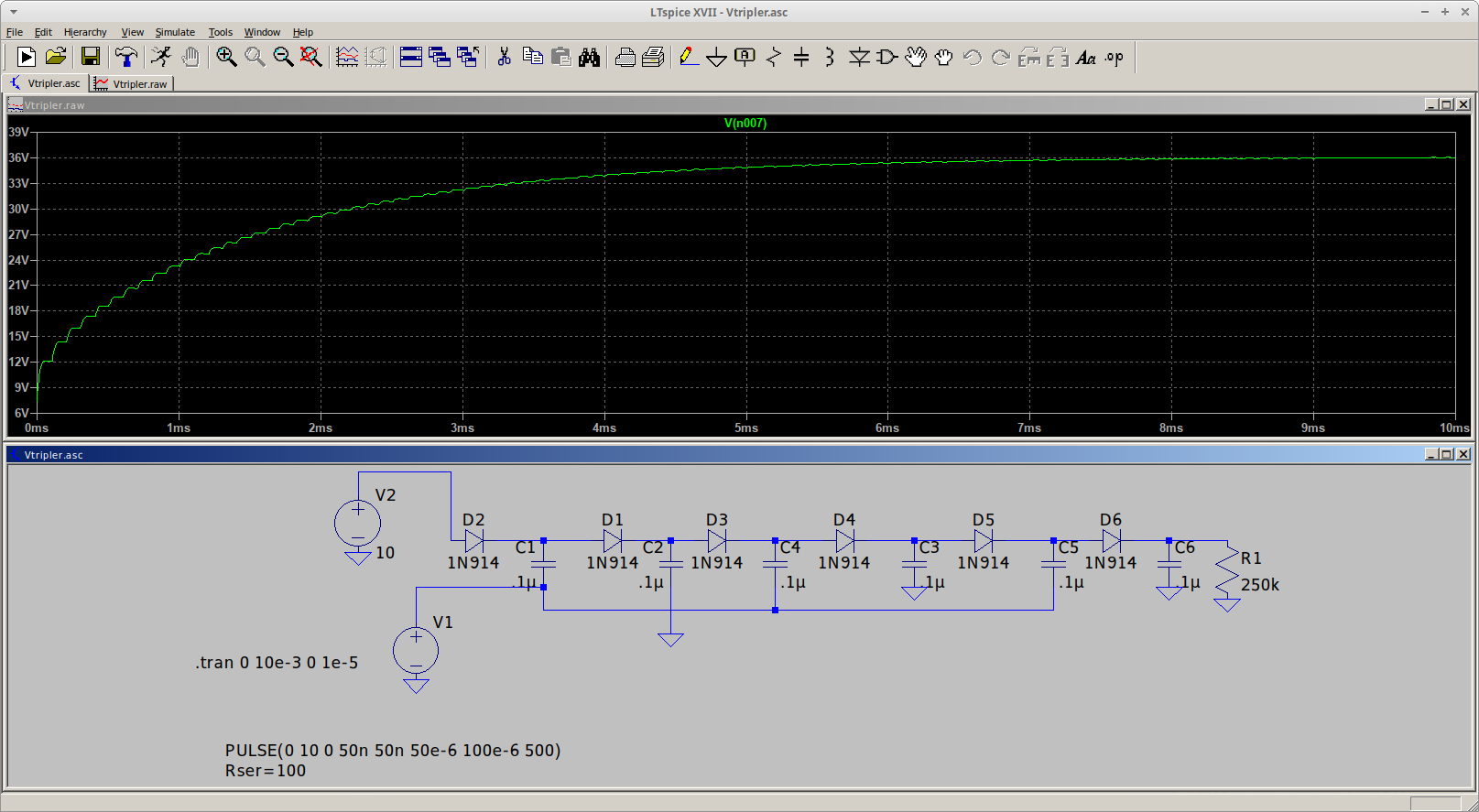
I went with a Dickson-style voltage multiplier that uses two inputs that switch between 0 and +10.  The two inputs are 180 degrees out of phase, so a CMOS buffer would work well for this.  Here's an LTSpice simulation of the voltage multiplier:


Due to the relatively small capacitors it takes awhile to come up to its full voltage output.  The simulation was done using 1N914 diodes to get an idea of what the actual voltage output would be, because the voltage drop across each diode reduces the output voltage somewhat.

Since the in-phase and out-of-phase inputs should be balanced for best performance, the oscillator in my actual voltage multiplier needs to have a 50:50 duty cycle.  But this isn't all that easy to achieve.  Most CMOS oscillators based on inverters do NOT have a 50:50 duty cycle.  The other thing I didn't like is that the "best" oscillator I found uses 3 inverters, which used up more gates than I wanted -- producing an unbalanced drive capability for the two inputs to the charge pump.  I really needed a 2-gate oscillator with a guaranteed 50:50 duty cycle.

I recalled that the old transistor-based astable multivibrator produced a pretty good 50:50 duty cycle, so I designed one using two CMOS buffer/inverters, and simulated it using LTSpice.  The circuit initially didn't work because the Spice simulation uses buffers that are exactly the same -- there's no circuit imbalance to get the oscillator going.   I found it necessary to use a pulse generator to kick things off.  The pulse generator just outputs 1 pulse so it doesn't interfere with the simulation after it turns off.

Here's the result:


Since one of the outputs has a 50:50 duty cycle and everything is symmetric, the other output has a  50:50 duty cycle as well.  My initial choice for the R's and C's didn't oscillate at 10KHz, my target frequency, but it was easy to come up with a correction factor (based on the CD4049 Spice model).  That said, my calculations produced:  F = .417/(RC).  This was for a 10 volt supply voltage.  If I drop Vcc to 5V the frequency drops a bit -- to around 7.7KHz.  This is because the buffers' threshold voltage doesn't change as Vcc changes.  Based on the application, the frequency variation would be less of an issue than the fact that the voltage multiplier's output would drop by a factor of 4.  So....no big deal.

My circuit frees up an inverter, only uses one more component than the 3-gate oscillator and has a duty cycle that is much closer to 50:50.  Pretty much a win as far as I'm conerned.

The main variation in the duty factor would be due to tolerance-related variations in the external R's and C's.  Easily addressed by using parts with tighter tolerances, or adding a trimming resistor in series with one of the R's.  The latter approach is NOT preferred because trimmers are more expensive than resistors, and, of course, it's necessary to adjust the trimmer.  Expense would be a hobbyist AND commercial-product related concern, the time needed to adjust the trimmer would be an issue for a commercial product.
 

Friday, March 15, 2024

Gamma Ray Spectroscopy/XRF update

 It's been quite awhile since I posted anything regarding my efforts toward coming up with an inexpensive XRF system.  I have built a lot of hardware and written a lot of software toward that goal, and....so far, have come up empty.  At this point I think it's due to the PIN xray detector -- it's just too noisy, and doesn't appear to have much, if any, energy resolution.  I worked on it pretty hard but....have come to the conclusion that it's not the way to go.  This decision was further cemented by my discovery that the detector is no longer being offered for sale as a standalone device.  It, or a similar-area device, can still be purchased but only in combination with a CsI(Tl) scintillator crystal.  Naturally, it also is more expensive.  And, since it has a very high dark current I still would expect it to be pretty noisy.

For these reasons I bought a used PMT/Scintillator off ebay.  It is a unit much like this, and can be a very good value if the PMT and scintillator are in good shape.  As-is it's not all that great for XRF usage but there is some good online information on how to modify one so it's compatible with the Theremino hardware and software.  But being a retired electrical engineer and dyed in the wool DIYer I decided to build my own high voltage power supply for the PMT, using a CCFL inverter board to convert 12 volts to 800-900 volts.  Due to lots of EMI coming out of the inverter and the necessity of achieving microvolt-level noise on the HV line that turned out to be quite a challenge.  I ended up using two separate 12V supplies -- one for the CCFL inverter, and a second one for the HV controller board.  The CCFL inverter was modified so its output could be better-controlled, and isolated from the controller board with an optoisolator.  I also made two aluminum enclosures for the inverter and controller, to further reduce EMI coupling from the inverter.

The whole thing was screwed down to a piece of wood, so this is a true "breadboard" style of construction:


The optoisolator circuit is between the two boxes.  The item with the blue tape on it is a home-made inductor to further isolate noise coming from the CCFL's control input line.  I modified the CCFL board by isolating the center tap of the transformer primary.  It normally is connected to the board's +12.  All of the online descriptions of using a CCFL as the heart of a HV power supply simply vary the supply voltage provided to the inverter board, but the one I bought would shut down if the supply went much below 12V.  I also lifted both of the secondary output pins because that completely isolated the CCFL's power supply from its HV outputs, which are routed to the controller board's HV rectifier/capacitor/filter network.

I used LTspice to design the optoisolator.  Here's the circuit diagram and simulation for one of my earlier versions:


The final design also includes a diode-connected PNP transistor in the emitter leg of the power transistor, to improve the low-current linearity of the circuit.  This is important because it turns out that my CCFL inverter doesn't need much input voltage to generate 900 volts.

Here's a photo showing my test setup, minus the HV power supply:


The Am-241 sources, detector and signal conditioning stuff is inside the aluminum box on the right.  The lead shielding is on the inside.  I'm using a Teensy 4.1 with a home-built 1MSPS 16-bit ADC to acquire the pulses.  The Teensy and ADC are behind the computer.  I'm using the Arduino IDE to develop the S/W.  I also am using a little Adafruit TFT to plot the spectums (when I get any that make any sense!).

Regarding the ADC, I figured out that the Teensy 4.1 has 16 contiguous I/O bits in one of its GPIO registers so that made it relatively easy to interface a fast 16 bit ADC to it.  Here's a photo of the ADC board, although in this case it's connected to a T4.0, which only has 8 contiguous bits available -- so the S/W has to grab 16 bits in two 8-bit "gulps" and combine them:

That's all for now.  I'm currently in the process of modifying my PMT's voltage divider.  Once that's done I will be pretty close to trying out the whole system with a detector system that is known to work well for XRF.  From there I get to see if my software is working right....


Wednesday, November 8, 2023

Creamy & Smooth Oat Milk

 This recipe is a variation on ones I found online.  I think it has a much nicer mouthfeel compared to other recipes, because in addition to the oats it contains fat of some kind, like butter or coconut oil (I actually like the coconut oil better).  It also is cooked slightly.  My recipe also adds a small amount of salt and sugar, but they are optional (but recommended).

Creamy Oat Milk

Makes approximately 1 quart of oat milk

2/3C rolled oats.  Not quick (pre-cooked) oats.

1/2 tsp salt

1 tsp sugar

1/2T butter or coconut oil.  They don't have to be in liquid form.

4C water, divided

Optional flavorings:  vanilla or almond extract.  I haven't tried cocoa powder, it probably would require more sugar to balance the bitterness contributed by the cocoa.  Dutch Process cocoa would be less bitter.  These flavors should be added after the oat puree is strained.

1.  Put the oats in a blender.  Add 2 cups water at room temperature, cover with the blender lid and allow to soak for 30 minutes.

2.  Blend on high for 30-60 seconds.  Strain into a bowl with a fine-mesh strainer, using the back of a large spoon to gently press down on the pulp.

3.  Add the remaining water, salt, sugar and fat to the bowl.

4.  Heat on High in a microwave oven, long enough to raise the temperature of the oat milk to 140F.  See Note below.  This step gelatinizes the starch, which gets rid of the gritty mouthfeel.

5.  Use a whisk to blend in the now-liquid fat.  The idea here is that the fat will form something like a roux where the fat globules are surrounded by starch so they will form a relatively stable emulsion.

Higher cooking temperature and more fat might make something closer to cream rather than milk, but if you over-do it you will likely end up with something that is more like pudding instead of milk.

Pour into a 1 quart jar and store in your refrigerator until ready to use.  Shake well before using.  Keeps for about 1 week.

NOTE  Our microwave oven takes about 5 minutes to heat the oat milk to 140F, but ours is an older, lower-powered one.  To check your microwave, place 4 cups of tap water in a bowl and "nuke" it for 4 minutes.  Stir to equalize the temperature and measure the temperature of the water.  If the temperature is higher than 145F, decrease the time by 30 seconds and try again.  If lower than 140F, increase the time by 30 seconds and evaluate the result.  You want to run enough room-temperature water in the bowl so it doesn't affect the result for each trial run.  The final test is to measure the temperature of a batch of your oat milk, since the actual volume of water will be slightly less than 4 cups.

Once you get the temperature to 140-145F you have characterized your microwave.  Make note of the time for the next time you make this recipe.

Tuesday, August 15, 2023

Low-E Materials for Solar Water Heaters

 As part of a liquid desiccant-based A/C system, an inexpensive heat source is needed to regenerate the liquid desiccant (LD).  One of the most-common approaches, used by Tech Ingredients for their exerimental systems, is a solar water heater.  In turn their design is based on one that Desertsun02 came up with, but they have a nice addition, which is to use low-E glass instead of plain glass.  The idea is to increase the efficiency by reflecting the longwave IR that's generated by the hot interior of the water heater back toward the water tubes -- rather than escaping out of the heater.

The problem is that low-e glass isn't all that easy to come by, at least in the searching that I have done.  Most vendors are selling complete low-e window units, while the best source for the odd piece of low-e glass is a custom house.

But it turns out that you can get low-e plastic film to put on a standard window, and it's not all that expensive, either.  So far, so good:  but there are DIFFERENT types of low-e films.  The most common is a film with a thin reflective layer of aluminum, which reflects both visible and IR.  Not useful for a solar water heater.  There is a class of so-called "transparent" low-e films that are available, which might be suitable.  Looking at reviews for these films indicates that the biggest challenge is applying the film without wrinkles or bubbles.  I suspect that the biggest challenge is that the film is being applied to a window that's already installed.  In my case I can lay the "substrate" glass flat, which should make it easier to properly apply the film.

The other potential issue is that the highest-efficiency LD based system requires that the LD be heated to at least 60C to regenerate it.  The film will be exposed to this temperature (via convection on the interior of the enclosure).   How long will it hold up??  Hard to say, since my application is far different from the intended purpose.

Addendum to the DIY A/C addendum

 It's been awhile but after reading my post regarding the use of an indirect-cooled evaporative cooler that's running a pseudo M-cycle scheme, I thought it good to mention that if the incoming water is below the ambient dew point (house interior), at least SOME parts of the system will likely have water condensation on them.  Hoses, any parts of the heat exchanger that isn't getting much, if any, air flow around it, etc.

One reason for re-visiting the subject is, of course, our current heat wave.  It got to 105 yesterday, and probably will get close to that today.  The day after it will "just" get up to 100.

The current outside air is at 77F/25C and 64% relative humidity.  According to my trusty psychrometric chart the wet bulb temperature is about 20C (68F) and the dewpoint is about 17.5C(~64F).  I have observed that the current air conditions are such that the wet bulb and dewpoint temperatures remain the same, as the air heats up.  That means that the humidity ratio (water/air mass) remains the same -- everything is so dry that there's little evaporation occurring!

Thursday, September 15, 2022

Not your usual dehumidifier, an Addendum

I ended my previous post discussing two different approaches that combine an M-Cycle(-ish) style chiller with a liquid desiccant dehumidification system.  One thing I failed to mention regarding the "bootstrap" approach, where the input air to the M-Cycle-Like (hereinafter called the MCL???) is dehumidified using LD, is that, if it works, it should output water that is chilled below the ambient-air dewpoint.  Simply because the water content of the input air is lower.  It remains to be seen if the end result justifies the added complexity of such a system.

The extra-cold water coming out of such a chiller might extract water from interior air to help dehumidify it -- but only if the inside heat exchanger is allowed to cool below the dewpoint.  Since we're running warm interior air through the HX I wouldn't count on it but, since up to this posting I haven't done anything other than make and characterize a plain-vanilla "swamp cooler" style chiller, who knows for sure.  I don't.  

I sort of want it to get cold enough, but don't at the same time, because if it DOES get cold enough to condense water I will need to add a way to take care of the water, rather than let it drip on our expensive wood floors!

Monday, September 12, 2022

Not Your Usual Dehumidifier

 Early in my quest for a DIY A/C system that might actually work in our (often) humid summers I came across a couple of youtube videos produced by Tech Ingredients that led me down an interesting path.

The first one, link here, introduced me to the idea of liquid desiccants.  It used liquid desiccant (LD for short) to pre-dry air that is cooled by flowing through an evaporative cooler.  It was fairly complex, using a second evaporative cooler to cool down the hot and regenerated liquid desiccant (more on this later in my post).  The second one, link here, is a system they built that was (hopefully) sized for a real-world application but didn't work all that well, possibly due to poor efficiency of their chilling tower and desiccant-solution tower.  I think that their spray head scheme didn't work too well -- it's likely that most of the spray quickly wound up flowing down the inner walls of the tube.  The laminar flow of the counter-flowing air then formed a "dead layer" that prevented good contact between the bulk of the air and the water or desiccant.  There are devices called "turbulators" that break up laminar flow into more-turbulent flow that might improve the performance of those towers.

So, what is liquid desiccant (LD) and why is it particularly useful for drying air for A/C purposes?

Folks should be familiar with one-shot desiccants like the silica gel packets found in prepackaged food, vitamins and other food supplements, or products like "Dry-Z-Air", used to capture moisture in locations like RVs, closets etc.  In the latter case, it actually uses the same chemical that is often used in LD applications -- calcium chloride.  I should add that all these desiccants can be regenerated by getting them hot enough to release the water they have absorbed.  I have purchased silica gel beads that actually have an indicator in them to show when they are exhausted and need to be baked so they can be re-used.  And I've seen at least one blog post where someone did something similar with calcium chloride, but it was a pretty dangerous process -- it's necessary to get CaCl pretty hot, and at that temperature it is very corrosive.

There are other solid desiccants like zeolites, some types of clay, molecular sieves etc.  They HAVE been used to perform continuous dehumidification by putting them in a rotating wheel or drum configuration.  One side of the drum is heated and air is passed through it.  The high temperature plus air flow pull the water out of the desiccant.  Then the wheel rotates out of the hot zone into a cool zone, so the desiccant can again absorb moisture.  Then inside air is passed through the wheel and dried.

Systems like this have been used in industrial applications where other process machinery generates high temperatures, so the heat is re-used.  Since the desiccant wheel would need to be heated anyway, this equals a savings in money.  They aren't used for private houses because houses typically don't have that kind of high-quality waste heat available; and they also are pretty large so there's enough capacity in the system to significantly dry the air.

In contrast, LD solutions -- typically they use something among the following:  lithium chloride, calcicum chloride, potassium formate or potassium acetate -- don't require really high temperatures to be regenerated.  In fact, they can be regenerated with systems that are very similar to (good) solar hot water heaters.  This is very attractive because typical demand coincides with lots of sunlight around.  Once your solar LD heater is built, the energy is "free".  Not quite because it has to be pumped through some other apparatus, but that doesn't take much energy to accomplish.

Most research in the field has found that lithium chloride is the most efficient LD.  It also is the most expensive so it's automatically eliminated from my consideration.  Among the rest, calcium chloride probably is the most efficient but it has some problems.  The first is that the solution, which is about 35-40% CaCl, is very corrosive so the pipes, pumps and heat exchangers used to heat and cool it have to be either plastic, stainless steel or ceramic.  This jacks up the price, at least for heat exchangers and pumps.  Of course, its corrosive nature is worse at elevated temperatures so a good design approach is to place our expensive pumps in the loop where the LD is at its lowest temperature.  This would right in front of the regenerator, which heats the LD up in order to shed the water it absorbed.  Another problem is that concentrated CaCl solutions have a very high freezing point, 40F and higher so it's necessary to keep the solution warm enough so it doesn't freeze and stop the system from working.  The other problem also is related to CaCl's  corrosive nature, and that is "carryover".  Since the dehumidifier designs have to put interior air and CaCl solution in intimate contact, there is the possibility of CaCl solution droplets being carried into the interior space, where they can corrode metal and degrade fiber -- like rugs, furniture, clothing....so the design of the absorber portion of the system is very important.  This, by the way, is another problem with the Tech Ingredients approach because they deliberately try to atomize their LD solution.   They are depending on some kind of post-absorber filtration setup, one way or another, to prevent that.  Absorbers that use air flowing at relatively high speeds are particularly susceptible to this problem.

Other LD solutions like potassium formate and potassium acetate are more benign in this regard, but they (1) aren't as efficient, (2) are more expensive; and (3) in the case of potassium acetate, its solution is reported to be very viscous so it is hard to pump it through the dehumidifier system.

It appears that the best way to prevent carryover is to use either packed-bed absorbers or so-called falling-film absorbers.  Unfortunately, the best media for packed beds is pretty expensive -- I calculated that a 1 cubic-meter absorber would require over $2,000 worth of media (basically specially-designed plastic whiffle balls).  So some kind of falling-film scheme looks best.

For developing different types of absorbers I'm planning on sampling the exit air with a high-voltage arc to ionize any calcium ions that are present, to be analyzed with (naturally, a home-made) visible-light spectrometer.  That will quickly reveal if the design has any carryover or not.

The Tech Ingredients' second design is meant to use the same LD solution to simultaneously cool the air and dehumidify it, in contrast to their first design which just dehumidifies the air entering an evaporative chiller.  However, their second design depends on an unassisted evaporative chiller to cool the LD solution -- not viable for a region that has high humidity, since the ability to cool the LD solution is limited.  The problem with their first design is sort of related, because they're using an unassisted evaporative cooler to chill the LD solution.  There are two alternatives that could improve the situation.  First, build an oversized chiller using an air pre-cooler to sorta-kinda replicate a Maisotsenko-cycle system; and use the chilled water to both cool the house and operate an LD dehumidifier's absorber in a separate system to control the house's interior humidity level.  The second is a kind of bootstrap system where the chiller is fed by an outside "feed" air flow that has been dehumidified by an LD system -- which in turn uses the same chiller water.  It's bootstrapped because as the chiller operates the dehumidifier front end, the dehumidifier becomes more and more effective -- it's helping to decrease the wet-bulb temperature because the feed air's RH is reduced by the dehumidifier, so the chiller water temperature goes down and further reduces the RH of the input air.  And so on.  I haven't found any papers that describe a system like this so at this point it is a wild guess on whether or not it is a real improvement or not.